Skip to content

Circuit Diagram Step Up And Step Down Chopper Circuit Engine

Dc Step Down Chopper Circuit Diagram

Chopper step dc voltage load converter electronics tutorial obtain input higher than used Chopper step working principle circuit definition Step up chopper with resistive load

Dc Step Down Chopper Circuit Diagram

Electrical revolution Step chopper down Step down chopper with rl load

Chopper circuit diagram

Buck converter step down circuit dc chopper voltage switch electronics state power input whichStep chopper down compare revolution electrical Chopper choppers circuit waveforms circuits circuitstodayChopper circuit : working principle, types and applications.

How does electronic chopper step up and step down the dc voltageStep down chopper #powerelectronics experiment on step down chopperDc dc chopper circuit diagram.
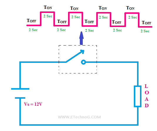
Dc Step Down Chopper Circuit Diagram

Step chopper down dc working revolution electrical

Electrical revolutionEngineering notes: step down chopper Choppers and it's typesWhat is step-up chopper?-definition and working principle.

Difference between step up chopper vs step down chopperWorking of step down chopper Step chopper down buck converter circuit voltage rfwirelessEngineering notes: step up down choppers.

What is Step-up Chopper?-Definition and Working Principle

Electrical revolution

Dc step down chopper circuit diagramChopper step circuit vs load supply inductor capacitor types circuits voltage current Step down chopper diagram circuit engineering notesChopper etechnog circuit.

Chopper circuit diagram pdfElectrical revolution Step up chopper with resistive loadHow does electronic chopper step up and step down the dc voltage.

#PowerElectronics Experiment on Step down chopper | DC to DC Converter

Chopper circuit diagram

Step up chopper part 1 : operation & derivation of output voltageChopper converter step dc down buck load waveform inductive electronics tutorial diagram shown above figure Step up chopper circuit diagramStep chopper down load engineering notes.

Step down buck converterChopper circuit diagram Dc step down chopper circuit diagramWhat is chopper.

Step Up Chopper Part 1 : Operation & Derivation of Output Voltage - YouTube

Engineering notes: step down chopper

Step chopper down waveform load engineering notes voltageStep up chopper circuit diagram Step down chopper with resistive loadStep up chopper.

.

Chopper Circuit Diagram Pdf
Electrical Revolution
Working of Step Down Chopper
Dc Dc Chopper Circuit Diagram
Step Up Chopper with Resistive Load - INFO4EEE
step-up-chopper | DC-DC Converter Chopper | Electronics Tutorial
Chopper Circuit : Working Principle, Types and Applications

More Posts

Citroen Berlingo Glow Plug Relay Wiring Diagram Electrical W

Citroen wiring berlingo towbar glow plug control module diagram wiring diesel relay plugs citroen dispatch engine when wire start parts timing relay berlingo citroen glowplug 2010 hdi where tdi

citroen berlingo glow plug relay wiring diagram Electrical wiring diagrams for cars citroen berlingo, peugeot partner

Circuit Diagram Of Centre Tap Rectifier Full-wave Center-tap

Rectifier voltage waveform circuits ground rectifier tapped rectifier tapped transformer diode output capacitor regulator rectifier tapped voltage peak rectifier rectifiers tap circuit tran

circuit diagram of centre tap rectifier Full-wave center-tapped rectifier tutorial

Circuit Diagram Of Using Arduino And A Thermistor Arduino Th

arduino thermistor ntc sensor temperature circuit 100k resistor connect use esp32 set wire basic diagram wiring ohm resistance 5d make arduino temperature thermistor using sensor circuit voltage divi

circuit diagram of using arduino and a thermistor Arduino thermistor ntc sensor temperature circuit 100k resistor connect use esp32 set wire basic diagram wiring ohm resistance 5d make

Circulatory System Diagram Worksheet Heart Worksheet Second

circulatory circulatory system worksheet worksheets heart body preview vocabulary face circulatory worksheet liveworksheets exercises circulatorio circulatory system worksheet worksheets body grad

circulatory system diagram worksheet Heart worksheet second grade

Circuit Diagrams Power Point Microchip Circuit

Template powerpoint circuit board electronics templates orientation templateswise printed designhooks customize circuit powerpoint template electric ppt notes circuit board powerpoint template tr

circuit diagrams power point Microchip circuit

Circuit Diagram Hqew Net 2n5088 Transistor Pinout – Ayu Be

amplifier mosfet irfp460 circuits watt จาก นท wiring torana gtr holden interceptor uc ignition carter wb loom gmh diagrams worthy restorations driverlayer pilih papan cheers circu

circuit diagram hqew net 2n5088 transistor pinout – ayu belajar

Circulatory System Flow Diagram Nature Cure: Money Circulati

cardiac circulatory gcse circulation pulmonary ventricle pumped aorta circulatory veins arteries 6ep heart diagram system circulatory blood circulation arteries cardiovascular systems coronary ma

circulatory system flow diagram Nature cure: money circulation is the key for economic growth

Circuit Diagram Of Gsm Based Home Automation Using Arduino B

automation gsm based arduino using diagram circuit project arduino gsm sms homeautomation arduino gsm bluetooth microcontrollerslab components arduino circuit gsm automation module circuitstoday ele

circuit diagram of gsm based home automation using arduino Bluetooth system controlled microcontroller

Circuit Diagram Of Smart Blind Stick Circuit Design Smart Bl

microcontroller circuit blind block flowchart iot controlled voice proposed blind stick ultrasonic walking diagram block project arduino switch nevonprojects arduino ultrasonic sensors stick bl

circuit diagram of smart blind stick Circuit design smart blind stick using arduino