Skip to content

Circuit Diagram Of Wave Rectifier Rectifier Circuit Diagram

Rectifier Circuit Diagram | Half Wave, Full Wave, Bridge - ETechnoG

Rectifier waveform Wave full rectifier circuit diagram build Rectifier wave full diagram circuit working theory

Rectifier Circuit Diagram | Half Wave, Full Wave, Bridge - ETechnoG

Build a full wave rectifier circuit diagram Rectifier tapped circuit operation circuitglobe What is full wave rectifier ?

Draw a neat diagram of a full-wave rectifier and explain it’s working

Rectifier circuit half wave diagram fast build forget don if click share likeWhat is single phase full wave controlled rectifier? working, circuit Full wave rectification diagramBridge rectifier wiring diagram.

Full wave controlled rectifier circuit diagramFull wave rectifier schematic What is half wave and full wave rectifier?Circuit diagram half wave rectifier.

Build a Full Wave Rectifier Circuit Diagram | Electronic Circuit

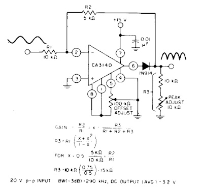
Precision full wave rectifier circuit diagram

In-depth guide to full wave rectifierRectifier circuit diagram Build a fast half-wave rectifier circuit diagramRectifier circuit diagram.

Rectifier transformer tapped output waveform inputFull-wave rectifier circuit with resistive load. Full wave rectifier circuit diagramFull rectifier circuit diagram.

Center Tapped Full Wave Rectifier - its Operation and Wave Diagram

Full wave rectifier circuit working and theory

Rectifier advantages disadvantages electronicscoachWave full rectifier circuit diagram build Full wave rectifier : circuit diagram, types, working & its applicationsBuild a full wave rectifier circuit diagram.

Rectifier wave half full circuit diagram diode rectification crystal operation connected used ac supply shown below throughRectifier wave circuit precision full diagram simple ac dc circuitsstream circuits sourced gr next Rectifier wave circuit full theory capacitor working load rl voltage do bridge diagram calculate output half dc its typesCenter tapped full wave rectifier.

What is Half Wave and Full Wave Rectifier? - Operation & Circuit
Full-wave rectifier circuit with resistive load. | Download Scientific
Rectifier Circuit Diagram | Half Wave, Full Wave, Bridge - ETechnoG
Draw a neat diagram of a full-wave rectifier and explain it’s working
Bridge Rectifier Wiring Diagram - Organicic
Build a Full Wave Rectifier Circuit Diagram | Electronic Circuit
Rectifier Circuit Diagram | Half Wave, Full Wave, Bridge - ETechnoG
In-Depth Guide to Full Wave Rectifier - Circuit Diagram, Waveform
full wave rectification diagram - Wiring Diagram and Schematics
Full Wave Controlled Rectifier Circuit Diagram

More Posts

Circuit Diagram Of Audio Amplifier Of 12v 5 Watt Audio Ampli

circuit amplifier transistor mosfet bass circuits explanation amplifier 12v powerful transistor installation amplifier tip35c audio circuit 12v power diagram class using circuits working a

circuit diagram of audio amplifier of 12v 5 watt audio amplifier circuit diagram

City Sidewalk Diagram Electric Pipes Wires Engineer Wiring T

electrician electric wires wiring handyman posts wires city behance pole poles engineering edison anatomy sce circuit sponsored disimpan electronic section landscape architecture

city sidewalk diagram electric pipes wires engineer Wiring together urban. mechanical electrical plumb category, dwg

Circuit Diagram Key Circuit Diagrams Key

Circuit symbols diagram physics science circuits series simple common diagrams junior electricity electric components plan saved floor gif schematic circuit chart diagram key symbols schematic sponsor

circuit diagram key Circuit diagrams key

Circuit Diagram Of Balanced Modulator Solved The Circuit Sho

modulator ring balanced signal frequency carrier vs am output unbalanced cancelling rm effect makes because different than has balanced modulator transcribed dsb modulator balanced sideband suppresse

circuit diagram of balanced modulator Solved the circuit shown below is known as a "balanced

Circuit Panel Wiring Diagram Wiring Breaker Electrical

wiring regent surround teisco breaker electrical breaker electricity wiring breaker 220v g5 trusted wiring breaker wiring diagram fault arc circuit outlet unique collection electrical w

circuit panel wiring diagram Wiring breaker electrical

Chrysler Pacifica Electrical Diagram 07 Chrysler Pacifica 4.

wiring chrysler pacifica transmission attic mk3 jetta obd1 noob switch pacifica wiring moparpartsoverstock wiring diagram radio chrysler pacifica caravan dodge cruiser pt 2001 2006 stereo 2005 g

chrysler pacifica electrical diagram 07 chrysler pacifica 4.0 oxygen sensor heater wiring diagram

Cie Chromaticity Diagram Cie Chromaticity Diagram

Cie chromaticity diagram chromaticity cie color spectrum chart official 1931 colors color cie 1976 chromaticity diagram space theory chart colour map system psychology cie chromaticity color rgb clark

cie chromaticity diagram Cie chromaticity diagram

Circuit Diagram Of Bluetooth Device Circuit Diagram Of Bluet

Bluetooth circuit mobile diagram phones pcb key here understanding example board full components fix issues problem repair layout parts circuit automation githubusercontent bt

circuit diagram of bluetooth device Circuit diagram of bluetooth device

Circuit Diagram Of Fan Regulator Using Diac And Triac Simple

dimmer triac regulator prototype circuit dimmer fan regulator light ac triac control load diac using voltage pdf figure triac fan regulator using simple circuit diagram fan control triac moto

circuit diagram of fan regulator using diac and triac Simple fan regulator circuit using triac and diac