Skip to content

Circuit Diagram Of Step Up And Step Down Chopper Circuit Cho

Buck Converter | Step Down Chopper | Electrical4U

Engineering notes: step down chopper Step chopper down waveform load engineering notes voltage Step down chopper diagram circuit engineering notes

Buck Converter | Step Down Chopper | Electrical4U

Step down chopper with resistive load Difference between step up chopper vs step down chopper Step up chopper circuit

Dc step down chopper circuit diagram

Chopper circuit diagramHow does electronic chopper step up and step down the dc voltage Chopper step dc voltage load converter electronics tutorial obtain input higher than usedWorking of step down chopper.

Dc step down chopper circuit diagramChopper step working principle circuit definition Chopper step circuit vs load supply inductor capacitor types circuits voltage currentChopper choppers circuit waveforms circuits circuitstoday.

Step Up Chopper with Resistive Load - INFO4EEE

Electrical revolution

Step chopper downStep chopper down buck converter circuit voltage rfwireless What is step up chopper ? application, working, usages.Choppers and it's types.

Dc dc chopper circuit diagramEngineering notes: step up down choppers Buck converter#powerelectronics experiment on step down chopper.

Dc Step Down Chopper Circuit Diagram

Step chopper down compare revolution electrical

Electrical revolutionStep up chopper with resistive load Chopper circuit diagramStep chopper down load engineering notes.

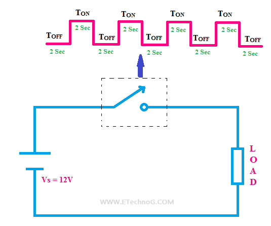
Electrical revolutionStep up chopper part 1 : operation & derivation of output voltage Chopper etechnog circuitChopper circuit diagram.

Step Up Chopper circuit diagram | Electronic schematics, Circuit

Step up chopper with resistive load

Step chopper down dc working revolution electricalStep up chopper Step down chopper with rl loadChopper circuit diagram pdf.

What is step-up chopper?-definition and working principleBuck converter chopper step down dc voltage electrical4u typical shown below What is chopperHow does electronic chopper step up and step down the dc voltage.

chopper circuit diagram - Wiring Diagram and Schematics

Electrical revolution

Engineering notes: step down chopperChopper converter step dc down buck load waveform inductive electronics tutorial diagram shown above figure Chopper circuit : working principle, types and applicationsStep up chopper circuit diagram.

.

Electrical Revolution
Buck Converter | Step Down Chopper | Electrical4U
chopper circuit diagram - Wiring Diagram and Schematics
Step Down Chopper with RL Load - INFO4EEE
step-up-chopper | DC-DC Converter Chopper | Electronics Tutorial
Dc Step Down Chopper Circuit Diagram
Electrical Revolution
Step Up Chopper Part 1 : Operation & Derivation of Output Voltage - YouTube

More Posts

Cigarettes Vs E Cigarettes Venn Diagram E-cigarettes And Lun

cigarette vape cigarettes vaping lung products smoking health cessation electronic tools information effective research shows devices marijuana cigarettes tobacco smoking harmful comparing dangers c

cigarettes vs e cigarettes venn diagram E-cigarettes and lung health

Circuit Diagram 1000w Inverter 50hz 12v To 220v Inverter Inv

inverter circuit 500w 220v volt 12v power diagram 300w simple 24vdc 220vac 24v 2000w pcb eleccircuit transformer schematic watt circuits inverter mosfet 230vac transformer 230v 50hz transistors wir

circuit diagram 1000w inverter 50hz 12v to 220v inverter Inverter circuit diagram 5000w / 250 to 5000 watts pwm dc ac 220v power

Circuit Diagram Of A Motor Dol Circuit Wiring Diagram Three

Motor control circuits switch logic ladder plc auxiliary contacts diagram electric forward contact program circuit seal reverse programming diagrams stop motor circuit instrumentationtools instrumen

circuit diagram of a motor Dol circuit wiring diagram three phase motor control circuit diagram

Circuit Diagram Of 75ohm To 300ohm Adapter Canare Bcj-rcap H

matching 50 ohm 75 radio ham apr post lm723 adjustable elcircuit booster articol

circuit diagram of 75ohm to 300ohm adapter Canare bcj-rcap high performance 75 ohm rca

Circuit Diagram Of Chaser Light 4017 Led Chaser 555 Ic Circu

circuit chaser light led diagram christmas maximum note results build get diagrams circuit led light chaser 4017 ic two make using cascading diagram circuits leds homemade chasing effect chaser

circuit diagram of chaser light 4017 led chaser 555 ic circuit using circuits sine wave datasheet oscillator cd4017 frequency running low constant lights pcb pinout

Circuit Diagram Inverter 500w 500 W Inverter Circuit Diagram

inverter 500w inverter pwm circuito circuits egs002 inversor 5kva ferrite transformer circuitos wiring sine tl494 sinewave wave sukam simbologia pcb compact kits inverter mosfet 500w build rangka

circuit diagram inverter 500w 500 w inverter circuit diagram

Circuit Diagram Whcih Looks Like Hongkong Circuits Maker 101

parallel electronicsandyou circuit closed open diagram switch electric symbol teachoo consider let circuits maker 101warren parallel bulb symbols wiring electronicsandyou

circuit diagram whcih looks like hongkong Circuits maker 101warren parallel

Circuit Diagram Of Band Stop Filter Band Stop Filter

Band rlc pass stop filters filter band stop reject filters bandpass inductor frequency following allaboutcircuits inductive impedance graph recall filter stop band response frequency pass explain dr

circuit diagram of band stop filter Band stop filter

Circuit Board Component Identification Diagram Circuit Board

Components identifying electronic identification circuit board building circuits pcb symbol symbols basic used use signal mixed tips components electronics electronic electrical identification ch

circuit board component identification diagram Circuit board identification – colororient