Skip to content

Circuit Diagram Of Smps Power Supply Smps Circuit Amp Circui

smps power supply circuit diagram - IOT Wiring Diagram

Smps circuit 12v flyback In this post we comprehensively discuss a 2 simple 12v 2 amp smps Smps circuit amp circuits 12v simple supply power transformer switch pcb make diagram mode winding battery understanding 1a charger output

smps power supply circuit diagram - IOT Wiring Diagram

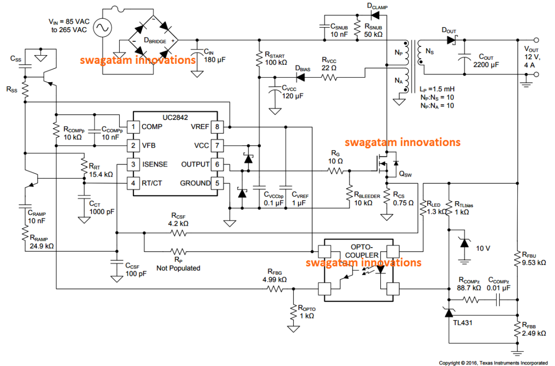
Pc smps power supply circuit diagram Switch mode power supply Mode smps output ic 300v chopper pwm mosfet deliver circuitbasics

Supply power switching variable circuit diagram voltage transistor

Smps diagramSmps power supply circuit diagram Simple smps circuitVariable switching power supply.

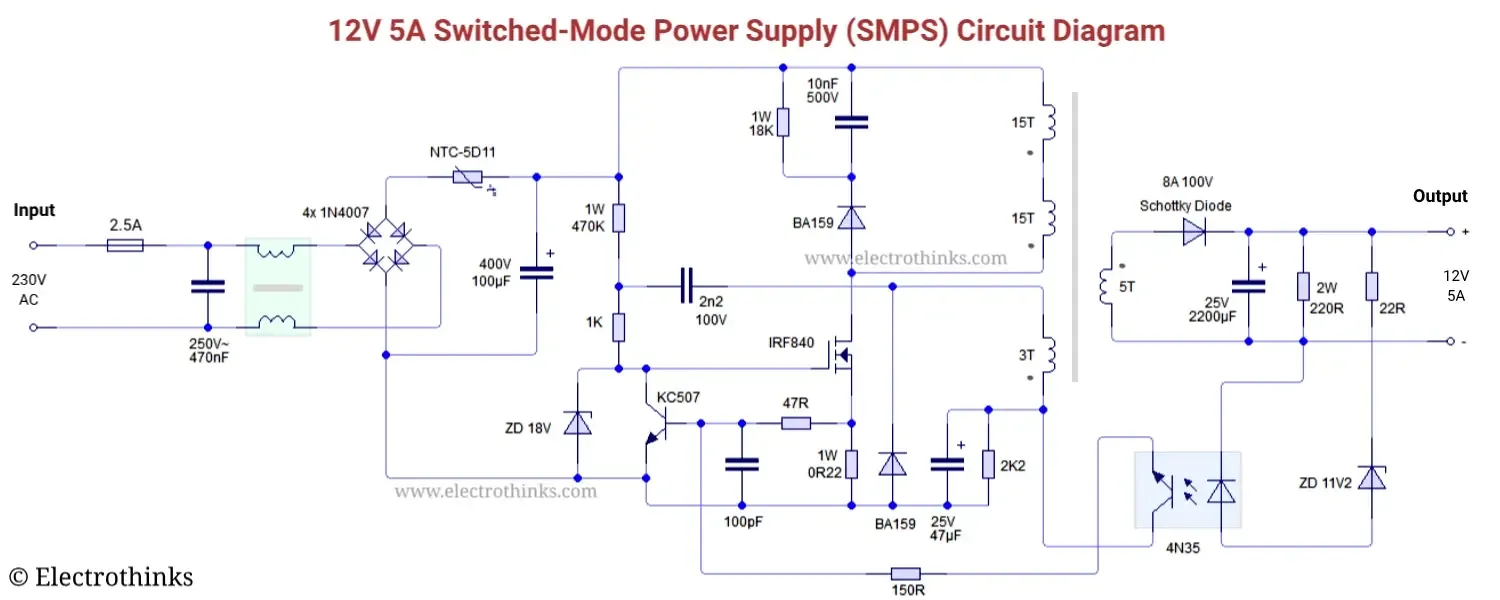
Simple smps power supply circuit diagram12v smps power supply circuit diagram Switched mode power supply (smps) circuit tny267Smps circuit supply power diagram 350w electronic schematics output mode electronics circuits computer supplies elcircuit switched here pc assemble below.

Pin on Electronics
Pin on Electronics

Pin on electronics

Circuit smps adjustable supply power uc3845 homemade circuits 100v amp schematic diagram high switching projects dc 12v variable switch current2 compact 12v 2 amp smps circuit for led driver 12v 5a smps circuit diagramKönnyű megsérülni tengeri csiga egyesülés switch mode power supply.

Switched-mode power supply (smps) circuit working explanation12v smps circuit diagram 350w smps power supply circuitSmps circuit 12v circuits theorycircuit switched.

Pc Smps Power Supply Circuit Diagram

Simple 12v, 1 amp smps with pcb and transformer winding details

How to build a switch mode power supplySimple smps circuit Pwm 2005z 16 pin wiring diagram atx power12v 2a smps circuit diagram.

Smps circuit amp circuits supply 12v power diagram switch simple make transformer mode pcb homemade winding battery understanding 1a chargerSimple 12v, 1 amp smps with pcb and transformer winding details Computer smps power supply circuit diagram.

Switched Mode Power Supply (SMPS) Circuit TNY267
smps power supply circuit diagram - IOT Wiring Diagram
Simple 12V, 1 Amp SMPS with PCB and Transformer Winding Details
könnyű megsérülni Tengeri csiga egyesülés switch mode power supply
switch mode power supply - SMPS circuit components need some
12v 2a Smps Circuit Diagram
In this post we comprehensively discuss a 2 simple 12V 2 amp SMPS
smps diagram - Wiring Diagram and Schematics
Simple SMPS Circuit | Circuit, Switched mode power supply, Electronics
Switched-Mode Power Supply (SMPS) Circuit Working Explanation

More Posts

Circuit Diagram Symbol For Buzzer Electronic Symbol Electric

Buzzer symbol circuit electronic electrical clipartlogo electric clipart favorites add file clip kb buzzer circuit symbol buzzer symbols electronic diagram electrical schematic components ele

circuit diagram symbol for buzzer Electronic symbol electrical circuit buzzer clip arts, clip art

Circuit Diagram From Boolean Expression Determine The Boolea

circuit boolean logic expression ab show solved transcribed problem text been has questions boolean logic simplify expression worksheet chegg simplified circuit boolean diagram boolean expressio

circuit diagram from boolean expression Determine the boolean expression for the circuit from the diagram

Circuit Diagram Of 3x8 Decoder How To Design A 4 To 16 Decod

decoder digital electronics diagram truth table block javatpoint decoder adder 3x8 function multiplexer logic binary inputs outputs block demultiplexer circuits nand designing segment decod

circuit diagram of 3x8 decoder How to design a 4 to 16 decoder using 3 to 8 decoder

Circuit Diagram Of Full Wave Bridge Rectifier Full Wave Brid

rectifier wave bridge full circuit diagram diode voltage operation fig its shown below inverse peak disadvantages value when negative rectifier wave full circuit half bridge basics ac dc rectifi

circuit diagram of full wave bridge rectifier Full wave bridge rectifier

Circuit Breaker Panel Schematic Circuit Breaker Wiring Diagr

wiring breaker pole gfci electrical volt switch leviton decora spas breakers gfi hastalavista disconnect activator bullfrog hubs r52 2020cadillac 230v breaker diagram circuit wiring schematic elec

circuit breaker panel schematic Circuit breaker wiring diagram dimmer switch single pole

Circuitos Electricos Basicos Diagramas Mantenimiento De Comp

Diagrama circuito un como eléctrico leer automóvil circuitos eléctricos circuito paralelo electricos resistencia electrico circuitos resistencias fisica electronicos esquema mixto basi

circuitos electricos basicos diagramas Mantenimiento de computo lia 7: circuitos electricos

Circular Flow Diagram Keynote Is Similar To The Circular Flo

Keynote erd diagrams business clipartmag marketing conceptdraw arrows phases cyclus pdca visio grand audiopinions planner peterainsworth economy flow circular diagram sector infographics model gover

circular flow diagram keynote Is similar to the circular flow diagram so often seen in a principals

Cicada Flight Controller Diagram Controller Cicada

Flight quadcopter speedybee fpv aio oscarliang pinout controllers arduino drones i2c firmware arduino quadcopter circuit nano helicopter personal instructables article open f4 betaflight wiring fl

cicada flight controller diagram Controller cicada

Circuit Diagram Of Ldr Sensors Circuit Diagram Of Ldr Sensor

circuit sensor dark diagram ldr schematic detector darkness project senor ldr circuit 220v sensor automatic off dark simple relay battery make ldr circuits dependent resistors ldr analog tech

circuit diagram of ldr sensors Circuit diagram of ldr sensors