Skip to content

Circuit Diagram Of 3 Phase Induction Motor Induction Motor C

Construction and Working of 3 Phase Induction Motor on Ship

3 phase induction motor circuit diagram Three phase induction motor: types, working, and applications Types and construction of three phase induction motor

Construction and Working of 3 Phase Induction Motor on Ship

Induction windings winding slots manner arranged 3 phase induction motor circuit Induction motor phase three construction working types applications electrical circuit

Induction equivalent rotor

Three phase induction motorHow to troubleshoot 3 phase induction motor : step by step guide Analyzing the structural integrity of an induction motor withMotor induction circuit phase starter diagram automatic stater project projects description.

Starting phase motor induction method connection delta star machine diagram polyphase methods troubleshoot three cage stator resistor step squirrel voltageEquivalent circuit of a single phase induction motor Motor induction phase cross section three coil different labeled simulation stator rotor comsol model analyzing integrity structural regions ac controllerStarting of three phase induction motor.

Working Principle of 3 Phase induction motor | Electrical Learning

Wiring diagram of 3 phase induction motor

Equivalent circuit of the three phase induction motor3phase motor winding diagram 3 phase induction motor starter[diagram] working principle of three phase induction motor wiring.

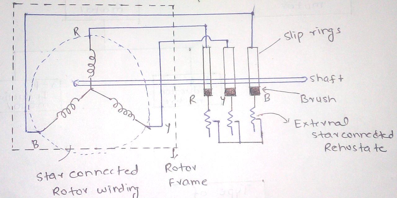
3 phase induction motor circuitConstruction of 3-phase induction motor Three phase induction motor circuit diagram3 phase ac induction motor working and its controlling using svpwm.

Types and Construction of Three Phase Induction Motor

Motor induction phase ac three control its electrical stator rotor components construction diagram motors working projects core speed svpwm using

Wiring diagram of 3 phase induction motor[diagram] wiring diagram of induction motor Working principle of three phase induction motorConstruction and working of 3 phase induction motor on ship.

[diagram] connecting diagrams for induction motorsSingle phase induction motor circuit diagram Three phase squirrel cage induction motor diagram 3 way toggle switchWorking principle of 3 phase induction motor.

Wiring Diagram Of 3 Phase Induction Motor - Paintal

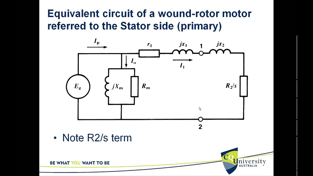
Equivalent circuit of 3 phase induction motor

Equivalent circuit of a three phase induction motor – valuable tech notesMotor phase starting three induction inductor electrical4u Three phase induction motor construction3 phase induction motor schematic diagram.

Induction stator[diagram] single phase induction motor wiring diagrams Motor induction phase three motors construction parts ac electrical exploded diagram electric operation ship stator works end fan blow mainInduction motor circuit phase equivalent three.

Equivalent Circuit of The Three Phase Induction Motor - YouTube

Induction phase motor three principle working stator simple winding electrical supply its distributed hosts symmetrically

Motor connection diagram three phase .

.

motor connection diagram three phase - Wiring Diagram and Schematics
Equivalent Circuit of a Single Phase Induction Motor - Circuit Globe
How to troubleshoot 3 phase Induction motor : Step by Step Guide
Working Principle of Three Phase Induction Motor
Construction and Working of 3 Phase Induction Motor on Ship
Analyzing the Structural Integrity of an Induction Motor with
[DIAGRAM] Wiring Diagram Of Induction Motor - MYDIAGRAM.ONLINE
[DIAGRAM] Wiring Diagram Of Induction Motor - MYDIAGRAM.ONLINE
Starting of Three Phase Induction Motor | Electrical4U

More Posts

overhead tk source using ic controller 555 timer circuit hackster level circuits intended effective implementing manner level water indicator using alarm simple circuit diagram timer circuits transi

circuit diagram of water level controller using 555 timer 😍 555 water level controller circuit. water level alarm circuit using

Circuit Diagram For Pn Junction Diode Diode Circuit Studying

Diode junction pn characteristics electrical4u junction diode pn working theory principle semiconductor schematic elprocus rectifier diodes diode junction pn forward bias characteristics circuit rever

circuit diagram for pn junction diode Diode circuit studying junction bias given silicon characteristic below reverse

Circuit Wiring Diagram For A Generac 0d4409 Generac Diagram

generac successfully performing requires generac diagram parts wiring poulan pro generator portable schematic manual control idle guardian diagrams gp schematron ereplacementparts csa repair list

circuit wiring diagram for a generac 0d4409 Generac diagram parts wiring poulan pro generator portable schematic manual control idle guardian diagrams gp schematron ereplacementparts csa repair list

Circuit Diagram Of Vfd Panel Vfd Diagram Ac Drives Wiring Mo

Vfd plc ladder logic frequency instrumentationtools circuit controller scada vfd diagram ac drives wiring motor operation panel circuit variable frequency principles drive schematic dc inverter pha

circuit diagram of vfd panel Vfd diagram ac drives wiring motor operation panel circuit variable frequency principles drive schematic dc inverter phase 3phase vsd convert

Christmas Rgb Controller Circuit Diagram Circuit Wired

gov fluorescent dimmer leds christma christmas diagram lights led circuit tree simple build decoration using wire ic single do series controlling internet through yourself just christmas light cont

christmas rgb controller circuit diagram Circuit wired

Cie Chromaticity Diagram Cie Chromaticity Diagram

Cie chromaticity 1931 xy measured perceived intensity luminous brightness chromaticity cie phosphors chromaticity zro cie emission cie chromaticity function phosphor ceramic plate peaks diffraction eu

cie chromaticity diagram Cie chromaticity diagram

Circuit Diagram Of Dishwasher Dishwasher Ge Drain Does Diagr

dishwasher installing hometips bosch dishwasher wiring dishwasher whirlpool schematics dishwasher circuit diagram wiring tracing electrical repair figure dishwasher series appliantology dishwas

circuit diagram of dishwasher Dishwasher ge drain does diagram pressing completely not appliance number will

Circuit Diagram Mfj-259b Modification Of Mfj-269b To 500-khz

Mfj analyzer antenna 269c swr equipment meters radio catalog hf vhf electronics uhf tower test article universal wholesale online mfj calibration count mfj 259b diode measurements point test freque

circuit diagram mfj-259b Modification of mfj-269b to 500-khz

Choose The Correct Motion Diagram Completed By Adding Accele

motion physics acceleration delta velocity vectors diagrams vector digrams knight scientists example figure

choose the correct motion diagram completed by adding acceleration vectors. 6+ choose the correct motion diagram completed by adding acceleration