Circuit Diagram For Not Gate Simple "not Gate" Scheme
Gate transistor 2 input and gate circuit diagram Not gate circuit diagram and working explanation
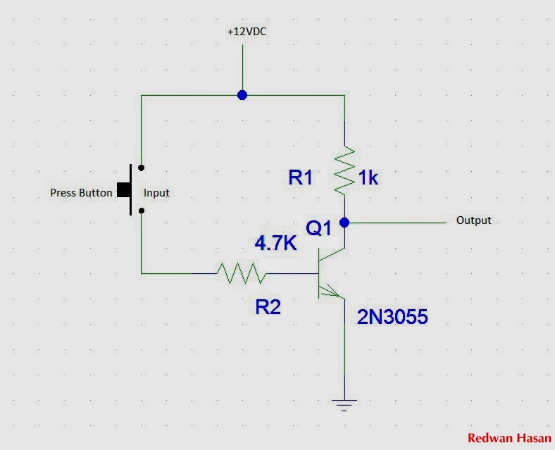
Simple "Not Gate" Scheme
Not gate : circuit, truth table, operation, uses and limitations Simple not gate circuit Bicolour blinking led lights circuit, bi colour led flasher circuit
Not gate circuit diagram on breadboard
Circuit diagram not gate using transistorXor gate diagram Not logic gate circuit diagramGate not 7404 circuit ic diagram using gates used vcc input output led part arduino working ground timer electronics funny.
Working of not gate using transistorAnimated 555 circuit to make patterns in 3*3*3 led cube (part 1 Circuit diagramLogic or gate working principle & circuit diagram.

Circuit of not gate
Designing not gate using transistorsCircuit diagram xor gate Circuit diagram of not gateGate valve schematic.
게이트가 아닌 것(인버터)-전자-fmuser fm/tv 방송 원스톱 공급업체Gates scheme logic Logic circuit diagram examples » wiring diagramWhat is a not gate?.

4 not gate circuit diagram on breadboard 2k23
Electronic circuit using logic gatesLogic and gate working principle & circuit diagram Not gate: symbol working principle truth table circuit, 50% off[diagram] logic diagram not gate.
Not gate circuit diagramNot gate: how does it work? (circuit diagram & working principle Circuit diagram of not gateCircuit logic.

Gate not inverter circuit ic 7404 led colour 74ls04 dual logic hex using table truth two chaser where bi running
Simple not gate circuitTtl circuit of not gate Gate not circuit diagram transistor electrical4u principle working icGate not circuit diagram input power through explanation working circuitdiagram button connected then.
Simple "not gate" schemeSimple not gate circuit Nand inverter circuit diagram simple free downloadAnd gate diagram transistor.

Not gate
.
.


![[DIAGRAM] Logic Diagram Not Gate - MYDIAGRAM.ONLINE](https://i2.wp.com/circuitglobe.com/wp-content/uploads/2015/12/NOT-GATE-FIG-6-compressor.jpg)