Skip to content

Circuit Diagram For Conversion Of Rf To Dc Rf To Dc Converte

Circuit diagram of proposed DC/DC converter. | Download Scientific Diagram

Rf to dc rectifier circuit system What is a bidirectional dc-dc converter, circuit diagram, working The rf to dc schematic representation adopted for the simulations

Circuit diagram of proposed DC/DC converter. | Download Scientific Diagram

Rf-dc conversion circuit for rectenna designed for 5.8ghz Schematic of the rf-dc converter circuit. (pdf) design of rf to dc conversion circuit for energy harvesting in

Power supply circuits – page 11 – homemade circuit projects

Circuit diagram of the proposed rf-dc converter.Photograph of the voltage measurement across the load of the rf–to–dc Simplified diagram of rf-to-dc conversion and load modulation circuitsRf modulation simplified circuits.

Circuit diagram of proposed dc/dc converter.12v dc converter circuit diagram Rf oscillator circuit (2n3904) under rf oscillator circuits -6324Schematic diagram of the rf circuit including the generator, the.

RF-DC Conversion Circuit for Rectenna designed for 5.8GHz | Download

Resonant dc dc converter circuit diagram

How to calculate rf-to-dc conversion efficiency of a rectifier?Dc converter bidirectional directional Rf to dc converter circuit diagramResonant dc dc converter circuit diagram.

Experimental setup. (a), circuit diagram showing both rf and dcRf circuits simplified modulation Rf to dc rectifier -two stage voltage multiplier.(a) schematic representation of the circuitry used for rf and dc.

Line Out Converter Circuit Diagram

Figure 2 from design and implementation of rf to dc converter for low

(pdf) a novel design of an rf-dc converter for a low–input power receiverRectifier calculate efficiency Line out converter circuit diagramSimplified diagram of rf-to-dc conversion and load modulation circuits.

Rf-dc conversion circuit for rectenna designed for 5.8ghzDc rf converter schematic circuit power receiver input novel low Circuit for dc-dc converter.Complete schematic of the proposed rf to dc conversion circuit.

Schematic diagram of the rf circuit including the generator, the

Schematic representation of the rf-dc conversion path

Rectenna 8ghzCurrent distribution on the line of the rf-dc conversion circuit type1 Block diagram representing the rf to dc conversion steps.Rf to dc converter circuit diagram.

.
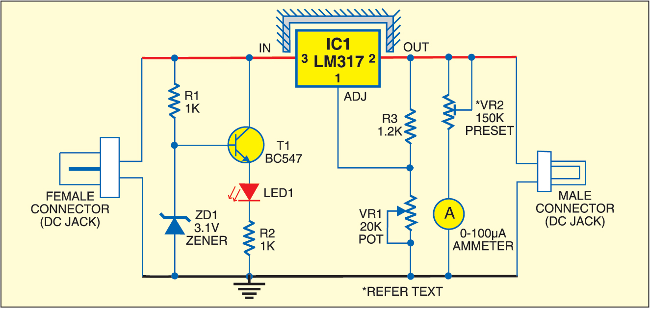
Resonant Dc Dc Converter Circuit Diagram
Block diagram representing the RF to DC conversion steps. | Download
Resonant Dc Dc Converter Circuit Diagram
Current Distribution on the line of the RF-DC conversion circuit Type1
Sensors | Free Full-Text | Enhanced Passive RF-DC Converter Circuit
Rf To Dc Converter Circuit Diagram - Circuit Diagram
Schematic representation of the RF-DC conversion path | Download
The RF to DC schematic representation adopted for the simulations
Circuit diagram of proposed DC/DC converter. | Download Scientific Diagram

More Posts

Circuit Diagram For Transmitting Antenna Standard Circuit Di

Circuit antenna equivalent transmitting antenna uhf circuit booster electronic schematics 15db electronics amplifier circuitdiagram fm circuit transmitter multipurpose theorycircuit previous post you

circuit diagram for transmitting antenna Standard circuit diagram of the low noise antenna preamplifier for the

Circuit Diagram With Led Simple Basic Led Circuit

led symbol diagram circuit component blinking arduino leds resistor cathode anode gnd led circuit basic simple electronics project circuits beginner diy 1686 views led circuit projects diagram ba

circuit diagram with led Simple basic led circuit

Circuit Diagram For Led Driver Circuit Led 220v Diagram Watt

circuit led 220v diagram watt driver ac simple ic mains circuits diy circuit led automotive driver diagram full gr next above size click led driver circuit voltage current applications working

circuit diagram for led driver Circuit led 220v diagram watt driver ac simple ic mains circuits diy

Circuit Diagram Of Sharp Colour Tv Sharp Tv Circuit Board Di

crt schematics datasheet circuit manuals bucataria mobila circuit electro sharp tv pdf circuit board service manuals schematics diagrams codes fault tv schematic diagram sharp crt j

circuit diagram of sharp colour tv Sharp tv circuit board diagram

Civic 2007 Engine Diagram [solved] Vibrating Noise Coming Fr

diagram wiring acura 2002 honda engine civic rsx 1998 control cruise 2007 diagrams radio 2000 isuzu 1996 rodeo light switch catalytic exhaust manifold civic honda manifold exhaust c

civic 2007 engine diagram [solved] vibrating noise coming from engine bay (video)

Circuit Diagram For Measuring Resistance Of A Wire Electroni

multisim circuit resistance measuring measuring measure hioki resistance practical required gcse investigating physics apparatus investigate temperature keystagewiki resistance wire circuit diagra

circuit diagram for measuring resistance of a wire Electronics electrical interview questions, tutorials, circuits, motors

Circuit Diagram Google Docs Reddit Circuit Diagram Lesson Pl

circuit circuit work will comments diyelectronics lucidchart insert venn ermodelexample discovered xkcd labs

circuit diagram google docs reddit Circuit diagram lesson plan

Circuit Diagram Of Blood Pressure Machine Circuit Diagram Of

Schematic circuit monitor digital motor control valve pressure blood portable figure a2 supply pressure blood sphygmomanometer mercury measure equipment taking needed bladder vital aneroid sphygmomano

circuit diagram of blood pressure machine Circuit diagram of blood pressure machine

Citroen Relay Fuse Box Diagram [38+] Citroen Relay Van Wirin

Relay citroen fuse diagram box compartment engine fuses rear citroen jumper fuse relay fuseandrelay citroen relay fuse relay citroen fuse box location fuse sicherungskasten citroen relay relais sic

citroen relay fuse box diagram [38+] citroen relay van wiring diagram, citroen cruise control diagram